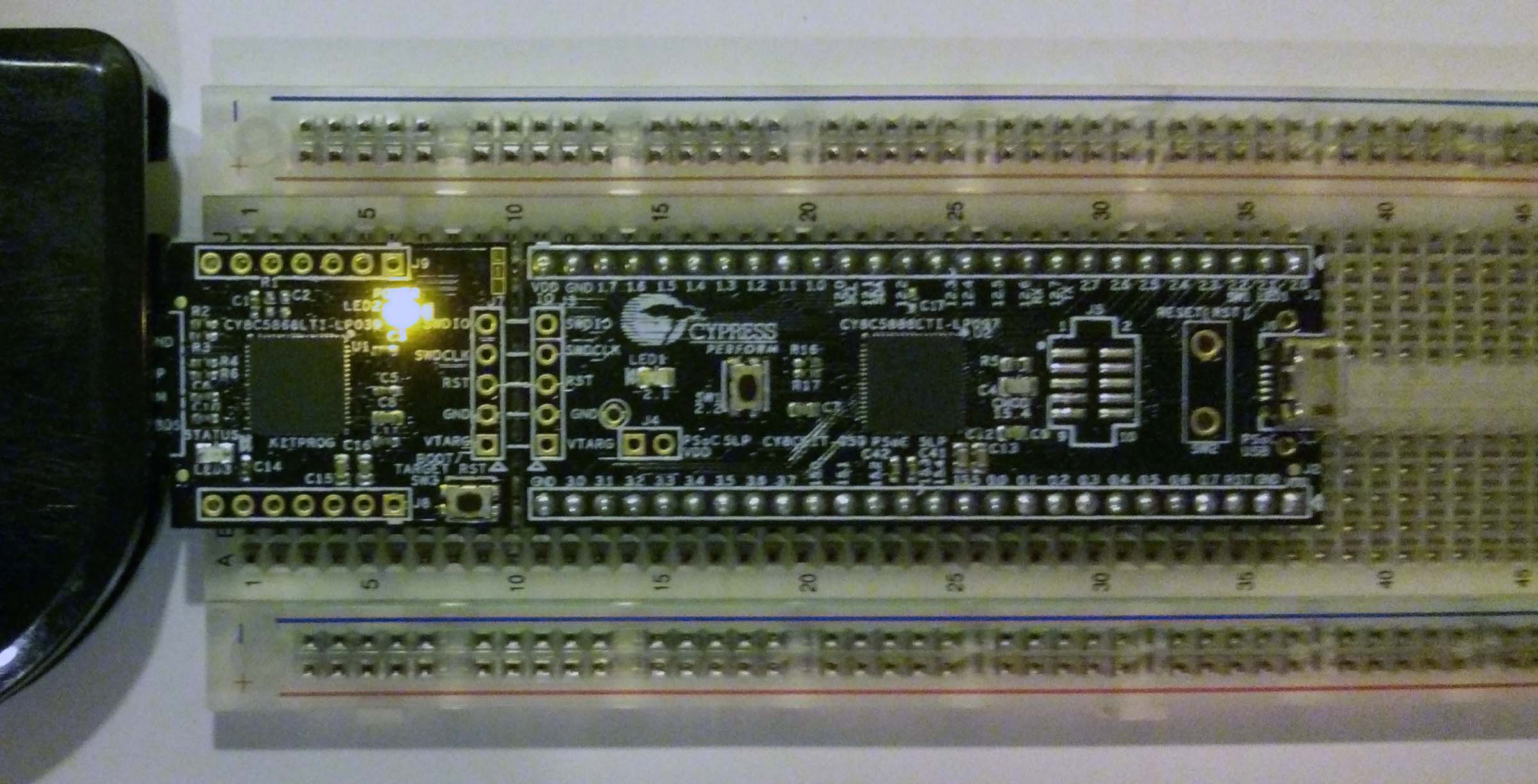
Previously, I wrote about the Cypress PSoC5LP microcontroller that I have been playing with. The CY8C5888LTI-LP097 on the CY8CKIT-059 dev-kit can be used to make a very crude radio transmitter. Today I will be explaining how to make some simple transmissions from a PSoC to a computer equipped with an RTL-SDR and SDR# acting as our radio receiver. We will be using configurable digital hardware to create the transmitter.
NOTE: If you decide to recreate my experiment, you should take a look at your country’s regulations for radio communicating devices. For example, the FCC in the United States allows hobbyists to create and operate up to 5 low power devices without a license as long as you follow some rules. Still, be responsible and don’t operate this for any longer then you need to know it works.
Using the configurable logic in the PSoC, I have created a simple radio transmitter that transmits a string of random bits using a 24 MHz carrier wave.
Let’s start with the mixer which in radio terminology usually means analog multiplier. Using a logic AND gate we create a similar effect since it acts like a digital multiplier. If both inputs to the AND gate are 1’s the output is a 1. If either of both of the inputs are 0 the output is a 0. The table below better illustrates this situation.
| Input 1 | Input 2 | (Input 1) AND (Input 2) | (Input 1) x (Input 2) |
| 0 | 0 | 0 | 0 |
| 0 | 1 | 0 | 0 |
| 1 | 0 | 0 | 0 |
| 1 | 1 | 1 | 1 |
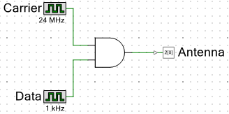
This produces a system where a carrier wave is output by the antenna when we want to transmit a 1 and no carrier wave is output when we want to transmit a 0. This modulation method is known as amplitude modulation which is what AM radio uses. Here is the circuit that transmits a 1 KHz tone using the AND gate mixer I described above. I have the Antenna output assigned to Pin 2.0 which is just soldered to a 0.1” header pin.
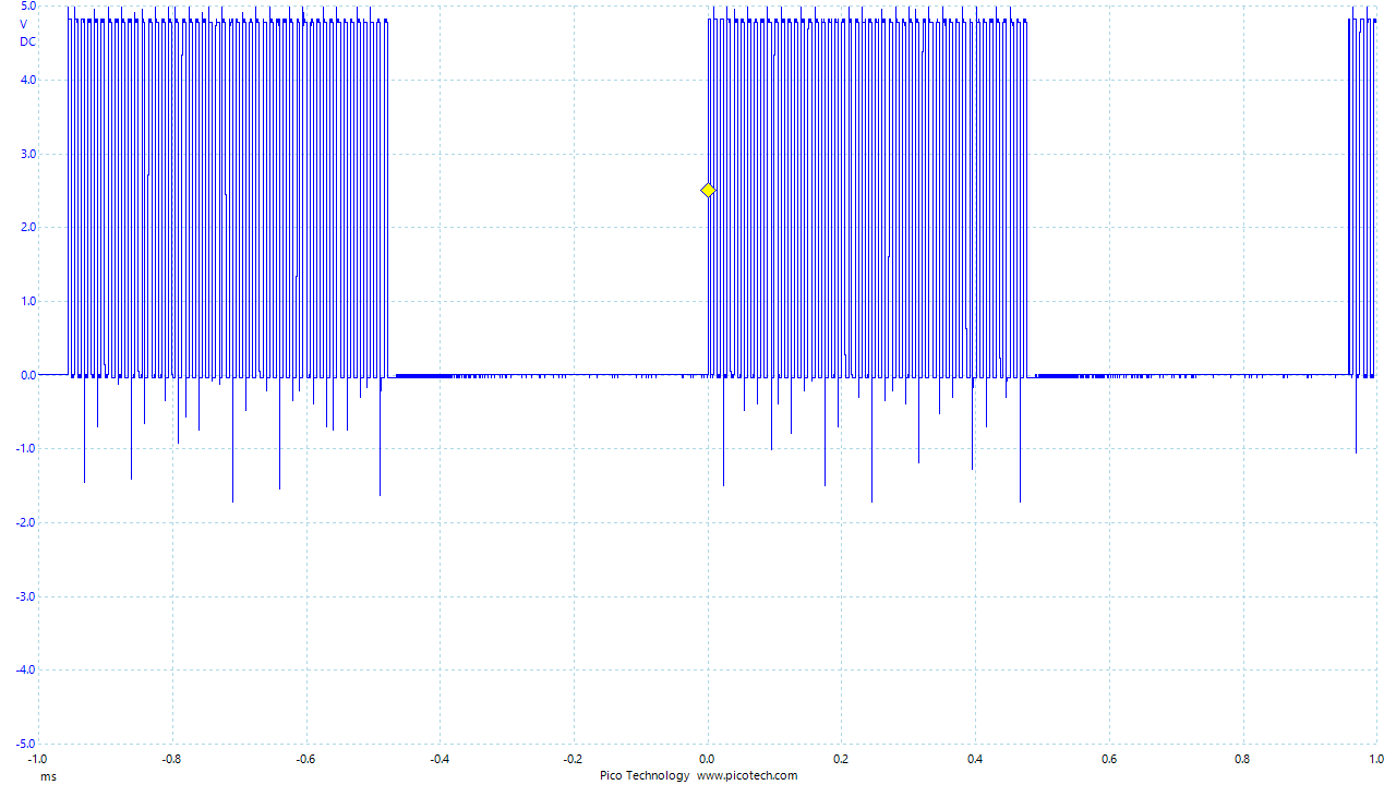
When the pin is probed using an oscilloscope the signal looks like what we expect. A 100% modulated AM signal. I lowered the frequency of the carrier wave to better show what is going on. Keep in mind, normally carrier waves are sine waves and not square waves since pure sines do not contain harmonics.
With the carrier wave increased to 24 MHz again, this is what the signal looks like in SDR#.
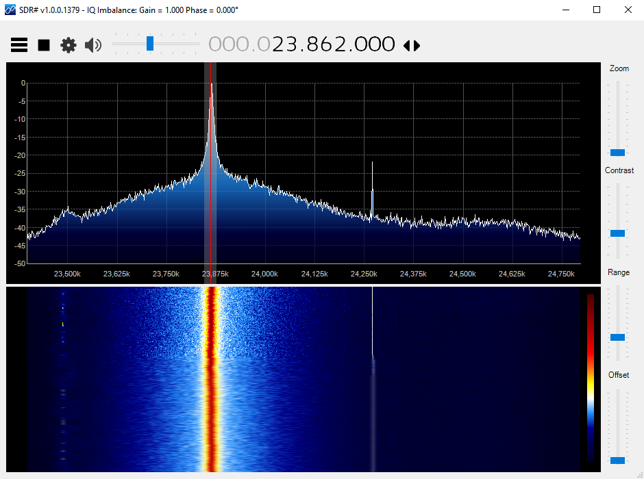
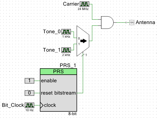
With SDR# set to AM demodulation, a clear 1 KHz tone can be heard. Now a tone is not very interesting, so let’s try to send some random data. Instead of just turning the tone on and off, I will transmit one tone for 1 and another tone for 0. This is known as Audio-Frequency Shift Keying, similar to normal FSK except we are not shifting the carrier wave around we are shifting tones in the lower frequency sub-carrier around. This is useful since I can transmit at a higher data rate if I wish. We can add more tones to transmit more bits per tone (or bits per symbol). This modulation scheme can be accomplished using a multiplexer or MUX, an input terminal is used to select an input, different tones, to pass to the AND gate which is acting as our mixer. The select terminal on our MUX is controlled by a Pseudo-Random Sequence Generator usually referred to as a PRBS generator. This PRBS generator produces random looking data for testing (It is actually implemented using a Linear Feedback Shift Register which is periodic in nature). Here is our new circuit the PRBS generator produces the next bit in its sequence every 10th of a second.
The PRBS generator needs a little bit of code to start it so here is the code as well.
#include <project.h>

int main(){
    PRS_1_Init();
    while(1);
}
With all that out of the way, here is what it sounds like.
[sc_embed_player fileurl=”http://138.197.16.247/wp-content/uploads/2015/10/SDRSharp_AM_PRBS.ogg”] SDR# – AM 2 Tone PRBS
Pretty simple huh? With this setup, I was able to receive the tones one floor above where the dev-kit was sitting. Maybe in the future I will write a receiver program in GNU Radio or something similar, but for now, this is just a cool demo.
Extra Notes: I should note that it might be a better idea to use clock dividers to generate the tones from the 24 Mhz clock. Using separate clock signals for that may not be the best design practice. Usually in a digital design like this you would also want to register your signals properly especially if the signal coming out of the AND gate is used to drive other logic since the signal coming out of the AND gate could contain glitches.
I have just started using the psoc and have been really impressed with their capabilities. I will have to try this out! Good job mate.
Thanks! It really is a very powerful chip and this is more of the hackish fun things to do. I hope to do a whole lot more with it in the future.