I recently picked up a Cypress CY8CKIT-059 to play with for about $10 from Mouser. The kit contains a CY8C5888LTI-LP097 chip that features an ARM Cortex M3 that can run up to 80 Mhz, pretty run of the mill. However, the chip also features a small amount of CPLD resources and configurable datapaths that can be used to implement any digital logic that you can fit in. Cypress calls these blocks universal digital blocks. You can implement your own logic blocks in Verilog or use Cypress’s IP cores that are included with PSoC Creator. The idea is to avoid predefining how many UART, I2C, SPI or other interfaces to include which gives you more freedom to choose the combinations of peripherals you need rather than using pin muxes like on Microchip PIC’s and Atmel AVR’s for example. With the PSoC 5LP you can have 5 UARTs if you wanted and you can put those UARTs on any GPIO pin you want.
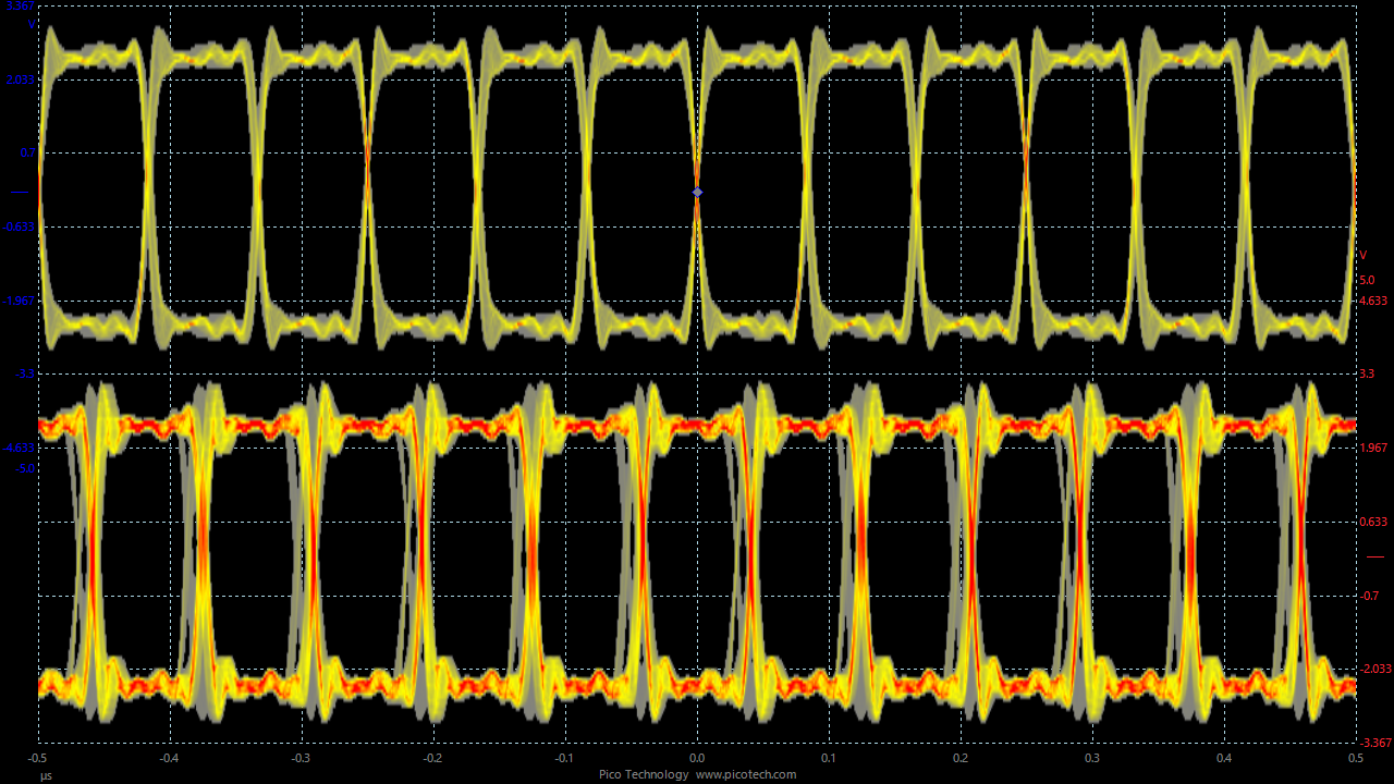
The PSoC is definitely an interesting platform to develop on. As an experiment, I decided to start on a logic analyzer that uses one of the available DMA channels to sample a test signal generated in the PsoC and stored it in RAM. When the buffer was full, the ARM core would transfer the data over a USB virtual COM port. I routed the interrupt signal from the status register holding the 7 inputs to an output on the PSoC and noticed a problem when looking at it on an oscilloscope. The sampling clock was jittering all over the place!
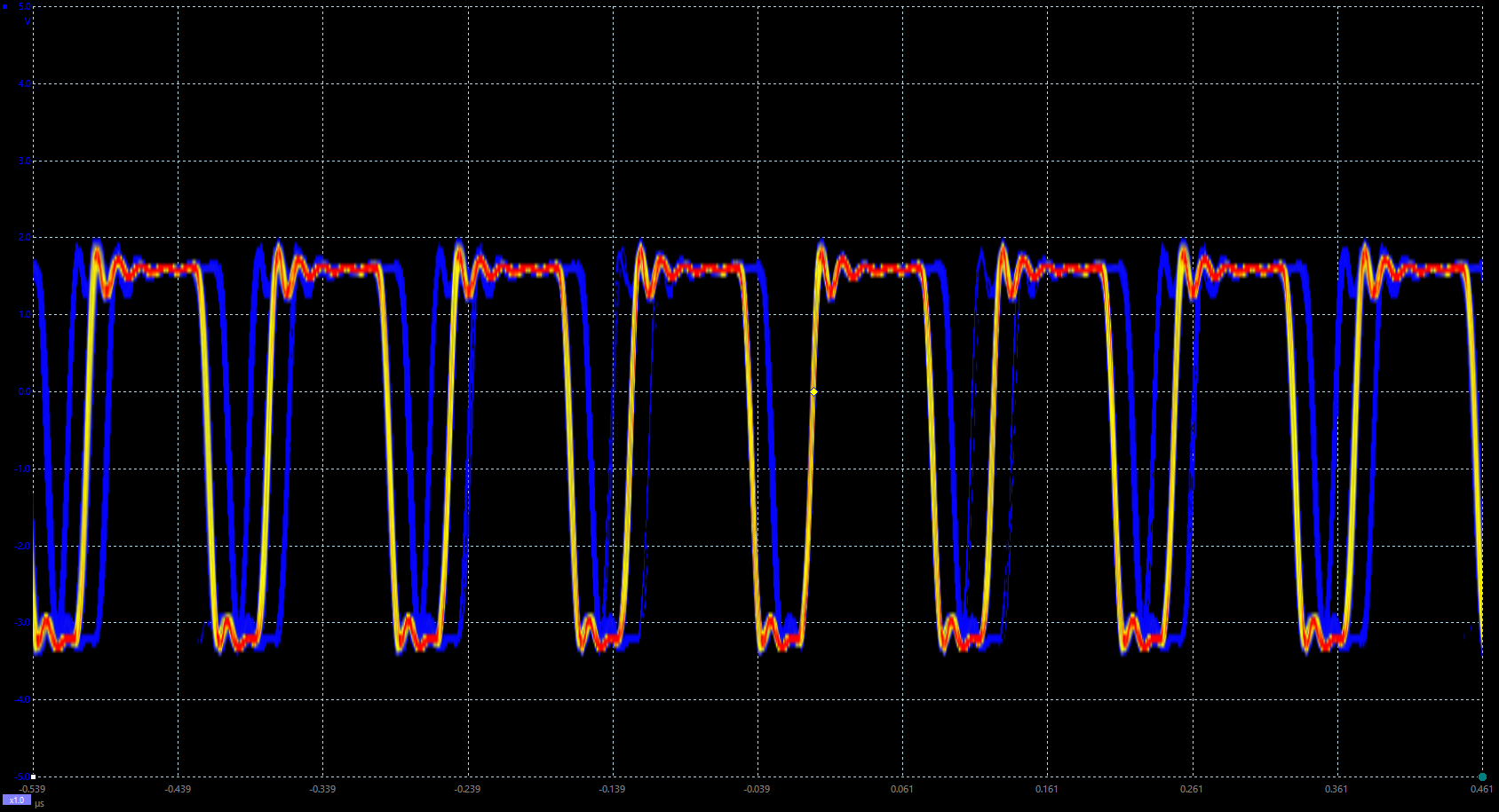
Something was definitely not right. As an example, here is a 6 MHz square wave derived from a 24 MHz oscillator in the PSoC called the Internal Main Oscillator (IMO). It should look nearly perfect at this time scale. What gives? After a little bit of Googling, it all made sense. This post on Cypress’s website explains a phenomenon that shows up when the clocks are configured incorrectly. I had derived the clock from the IMO but told the system to synchronize the clock to the Master Clock (MCLK). Since the MCLK was generated by a Phased Locked Loop (PLL) driven by the IMO, it has lost correlation with it. Since we synchronized the derived clock with the MCLK even though they have no correlation with each other, the derived clock jumped around when the synchronization occurred when the MCLK’s edges did not line up with the derived clock’s edges. By configuring the derived clock to work without synchronization to MCLK as suggested by the Cypress website, I get much better looking sampling clock.
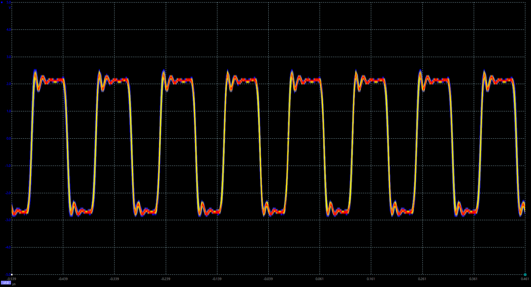
It should be noted however that this is not a perfect solution. There is a very good reason to synchronize uncorrelated clocks in a digital system. It ensures that events in the digital system occur at the same time in expected ways. Without synchronization it is possible for changes in signals crossing clock domains to be delayed or experience metastability. This can still create sampling jitter that can cause problems. The best solution to this problem is to derive your clocks from MCLK instead of the uncorrelated IMO clock. In this configuration it does not matter if you enable synchronization or not since the clock edges will always line up.
One thought on “PSoC – Intro and Clock Configuration”