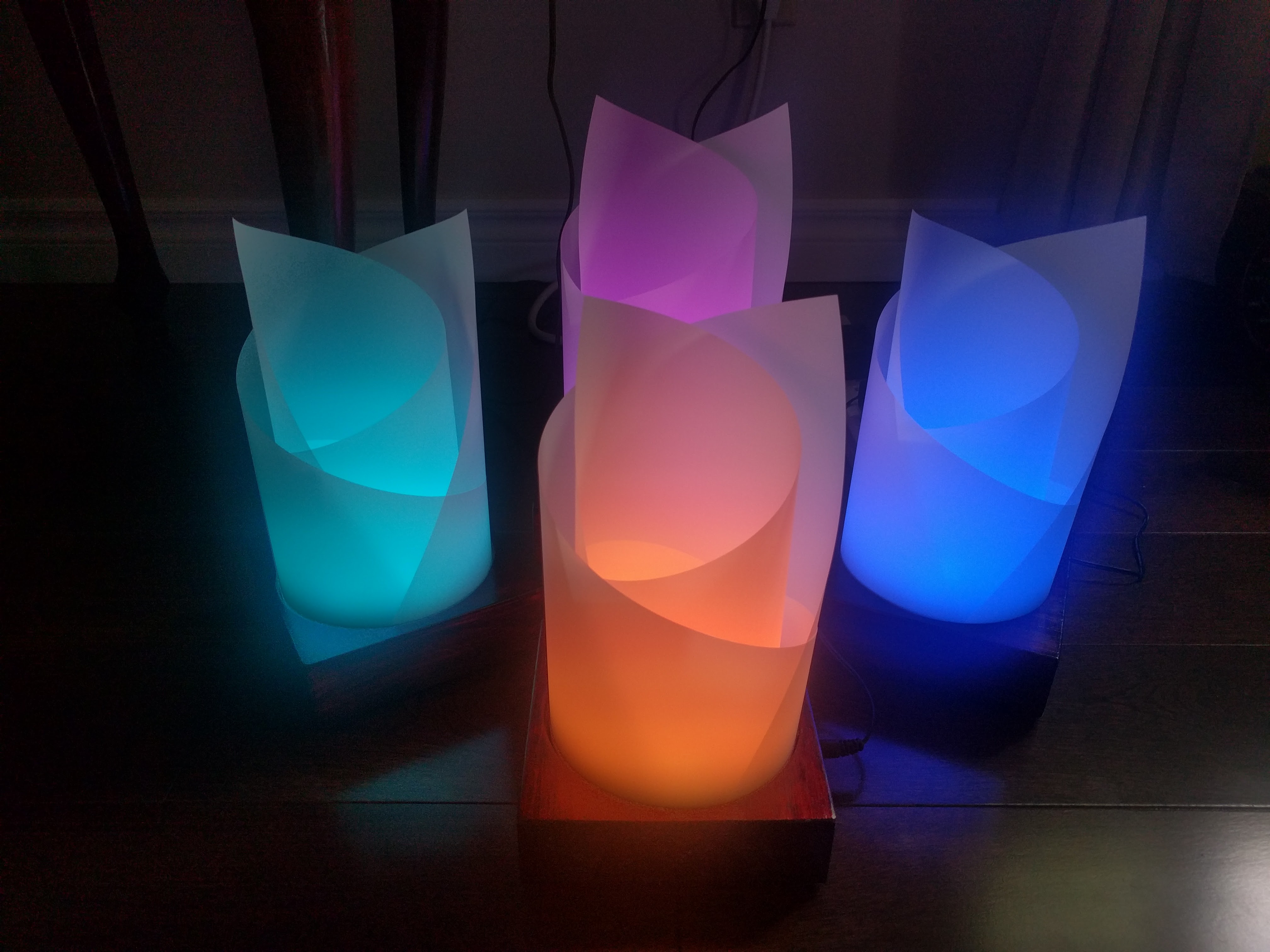
As a gift to my sister and her husband for their wedding I developed the electronics and firmware for a table centerpiece. The product was developed using tools and materials already familiar to me to tighten the development cycle so some component choices were not ideal but were chosen because I already had programmers on hand, code already written, or schematic and footprint libraries already created for past projects. This significantly de-risked manufacturing as many components of the product were already verified to be working giving me confidence to order boards and parts for twenty of these lamps all at once. Developed in about two weeks and all twenty assembled in a weekend this project was completed quickly as the big day was rapidly approaching when I returned to Canada after my internship in California summer of 2016.
Electrical Schematic Design
Microcontroller
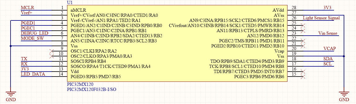
A PIC32 MX120 in an SO-28 package was chosen to run the firmware to drive the LEDs. The PIC32 is overkill for this application but I already had a PICKit3 on hand and code written to get the SPI peripheral up and running. The SPI peripheral was exploited to avoid the need for more complex timer interrupts to drive the one wire serial interface of the LEDs. This is a well-known technique used to drive WS2812b like LEDs using DMA, no DMA was used for this project as the number of LEDs driven is so low but the use of SPI still reduces complexity in the firmware. To ease hand soldering the SO-28 package was chosen. Though not originally chosen for this feature, the PICKit3 Programmer-to-Go functionality proved to be a time saver when flashing firmware to all twenty boards.

A 6 pin 0.1″ header was used for programming, during board assembly no header was soldered on. I simply put male header pins into the PICKit3 and pressed it up against every board to program them using Programmer-to-Go and an external power supply plugged into each board.
RGB LEDs
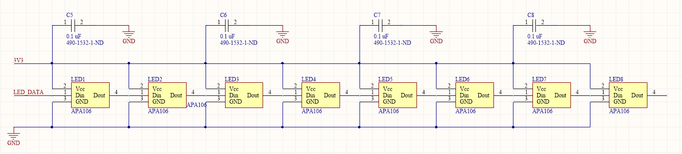
APA106 LEDs in a 5mm frosted package was chosen to hopefully avoid ugly bright spots in the lamp shade. The APA106 LEDs can be purchased for a low cost on AliExpress. They use a one wire protocol that is very similar to WS2812b based LEDs sometimes known as “NeoPixels”. The APA106’s simply daisy chain acting like a shift register. I added a 0.1 uF capacitor on the 3.3V line powering every other LED for good measure but they were probably unnecessary.
Power Supply
Power was supplied by four AA batteries in series wired to the board at the wedding. When the lamps were given away the battery box was cut out and a 5V AC power adapter was included to allow battery-less operation using the 2.1mm jack making this lamp a nice decorative night light that can be left on all the time.
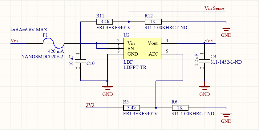
An STM LDFPT-TR adjustable voltage regulator was chosen for its low dropout voltage of only 200 mV at full current allowing long operation on batteries to avoid having the lights die during the evening. This was probably not needed as the power draw by the system was very low and the AA’s were barely drained by the end of the day. A surface mount fuse was added for short circuit protection and a voltage divider added to allow input voltage sensing by the PIC32 however this was never implemented.
Mode Switch
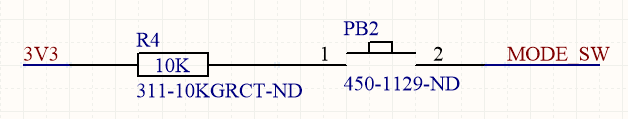
A small push button with a pullup resistor was added to allow cycling of the color of the lamp if desired.
Expansion Header
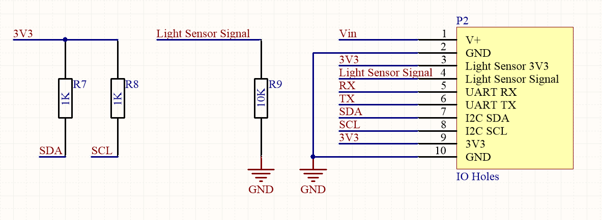
An expansion header with an input for a CdS light sensor, I2C with associated pull up resistors, and UART was added to allow future expansion and hacking.
Circuit Board Design and Assembly

The board layout was created in Altium. Dividing lines were created on a mechanical layer to allow me to align the LEDs at 45 degree angles to each other. Silkscreen graphics were vectorized by one of my sisters good friends from artwork my sister had created back in her undergraduate days. Conversion to silkscreen lines from the PNG file exported from Adobe Illustrator was done with the PCB logo script included with Altium Designer. Instructions on how to use this script are at http://techdocs.altium.com/printpdf/23168.
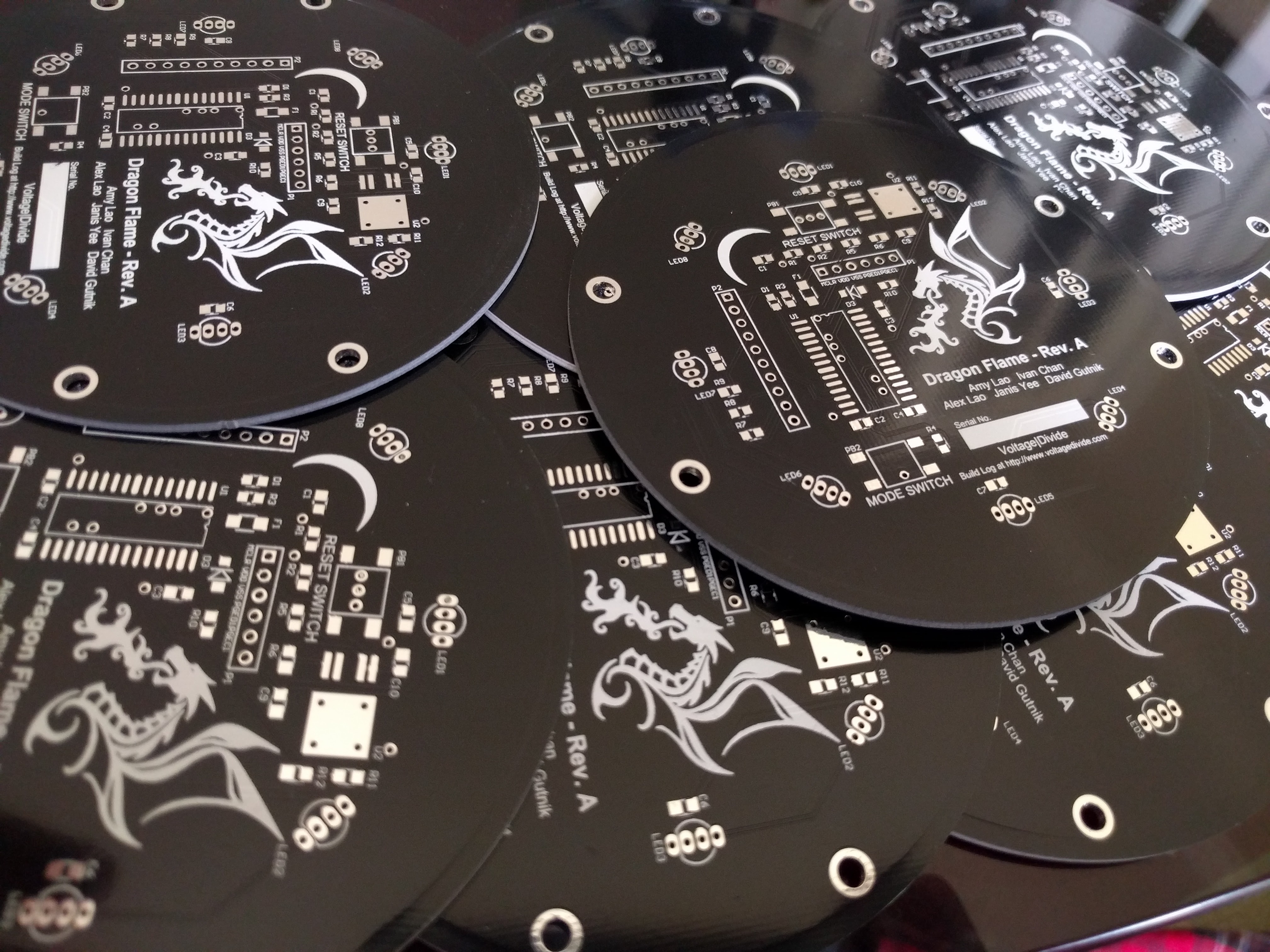
The board designed was 10cm in diameter and manufacturing was done by Elecrow using their 20 piece 10cm x 10cm prototyping service. The final cost of each bare board was about $2 USD. The boards were of reasonable quality and arrived in Canada in about 2 weeks from order. I saw small solder mask flaws where a few 0.5 mm diameter spots of copper were not covered. This was alright for this board but may not be acceptable for boards that contain finer pitched components.
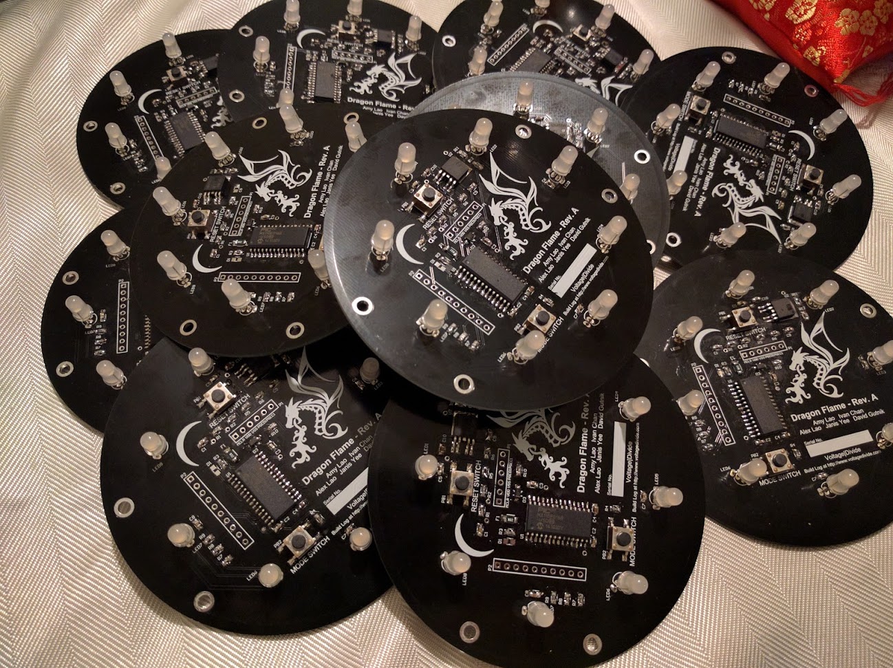
Electrical assembly was done in about a day with one person sorting through components and one soldering. A small amount of pen flux was used to assist with the denser joints but overall minimal flux was used to reduce the amount of board cleaning that was required to make the boards presentable.
Firmware
Time was running short so the firmware was hastily written using some old code developed for the Noiseblaster32 digital audio player I developed with Devon Andrade during the Summer of 2015. (https://github.com/andrade824/NoiseBlaster32)
As I mentioned before the SPI peripheral is used to generate the 1 wire signal used to drive data into the LEDs. According to the datasheet a high time of 0.35us and a low time of 1.36 us represents a 0 and a high time of 1.36 us and a low time of 0.35 us represents a 1. A low time of 50 us will trigger a reset of the bus and the data shifted in will be latched. The datasheet says the timing must be within 150 ns but I found elsewhere online showed that the timing does not need to be that close.
uint8_t SPI_Write(uint8_t data) {
    SPI1BUF = data;                 // write to buffer for TX
    while(!SPI1STATbits.SPIRBF);    // wait for transfer to complete
    SPI1STATbits.SPIROV = 0;        // clear any overflow.

    return SPI1BUF;                 // read the received value
}
Since the timings do not need to be exact I decided to play around. I found an SPI bus clock frequency of 5 MHz works well. A 5 MHz clock has a period of 200 ns, so an SPI byte write will generate a 1.6 us cycle. Writing 0xE0 (1110 0000) to the SPI peripheral generates a high time of 0.6 us effectively writing a 0 to the 1 wire bus. Writing a 0xF8 (1111 1000) to the SPI peripheral generates a high time of 1 us. In hindsight using 0xC0 for 0 and 0xFC for 1 would have generated closer timings but it didn’t seem to matter as the lamp works fine.
void LED_Write_Array(uint8_t data[][3], uint8_t NumLED) {
    uint8_t i;
    uint8_t j;
    uint8_t k;

    for (i = 0; i < NumLED; i++){
        for (j = 0; j <= 2; j++){
            for (k = 8; k > 0; k--){
                if((data[i][j] & 1<<(k-1)) == 0 ) {
                    SPI_Write(0xe0);
                }
                else {
                    SPI_Write(0xf8);
                }
            }
        }
    }
}
To perform a bus reset to latch the data I write 0x00 to the SPI peripheral 8 times which generates a low time of 12.8 us, much less then the 50 us the datasheet says is required but again this worked fine.
void LED_Latch() {
    uint8_t i;
    for (i = 8; i > 1; i--){
        SPI_Write(0);
    }
}
Timer 1 on the PIC32 with a 256x pre-scaler is used to generate a 1 kHz refresh trigger. This 1 kHz trigger is used to update the LED data.
void InitTimer1000Hz() {
    OpenTimer1(T1_ON | T1_SOURCE_INT | T1_PS_1_256, (GetSystemClock()/256)/1000);

    // Set up the timer interrupt with a priority of 2
    INTEnable(INT_T1, INT_ENABLED);
    INTSetVectorPriority(INT_TIMER_1_VECTOR, INT_PRIORITY_LEVEL_2);
    INTSetVectorSubPriority(INT_TIMER_1_VECTOR, INT_SUB_PRIORITY_LEVEL_0);
}
I decided to smooth the brightness transition by implementing what I call the LED Framebuffer and LED Setpoint. LED Framebuffer array stores the RGB values currently being displayed on the LEDs, the LED Setpoint array stores the target value. A fraction of the difference between the LED Framebuffer and LED Setpoint is taken and added to the current LED Framebuffer value. Updating the LED Framebuffer value is performed every cycle at 1 kHz, a random value is generated for the LED Setpoint every 50 cycles, a button is also sampled to shift the base colour of the light.
void main() {
    SYSTEMConfig(GetSystemClock(), SYS_CFG_WAIT_STATES | SYS_CFG_PCACHE); //Configure for maximum speed
    // Enable multi vectored interrupts
    INTEnableSystemMultiVectoredInt(); //Do not call after setting up interrupts

    TRISBbits.TRISB12 = 1;   // set RB3 as an input

    mPORTBSetPinsDigitalIn(BIT_3);
    CNPDBbits.CNPDB3 = 1; // Enables internal pull-down resistor on pin RB3

    mPORTBSetPinsDigitalOut(BIT_2|BIT_5);
     PPSUnLock; // Allow PIN Mapping
    PPSOutput(2, RPB5, SDO1);
     PPSLock; // Prevent Accidental Mapping

    // Init the spi module for a slow (init) clock speed, 8 bit byte mode
    SPI1CONbits.ON = 0; // Disable SPI for configuration

    SPI1BUF;    // Clear the receive buffer
    SPI1STATbits.SPIROV = 0;    // Clear the receive overflow bit
    SPI1CON = 0x260;    // Master, CKE=0; CKP=1, sample end
    SPI1BRG = 3;  // Divide by 8. SCK = Fpb/(2 * (BRG + 1))

    SPI1CONbits.ON = 1; // enable

    srand(0);

    uint8_t led_framebuffer[8][3] = {
                                    {255,50,0},
                                    {255,50,0},
                                    {255,50,0},
                                    {255,50,0},
                                    {255,50,0},
                                    {255,50,0},
                                    {255,50,0},
                                    {255,50,0}};

    uint8_t led_setpoint[8][3] = {
                                 {255,50,0},
                                 {255,50,0},
                                 {255,50,0},
                                 {255,50,0},
                                 {255,50,0},
                                 {255,50,0},
                                 {255,50,0},
                                 {255,50,0}};

    uint8_t random;
    uint8_t i;
    uint8_t j;
    uint8_t new_setpoint_countdown = 50;

    InitTimer1000Hz();

    uint8_t color[3] = {255,70,10};
    uint32_t total_color = 0xffffff; //B,G,R

    int8_t delta_color[3] = {5,0,0};

    while (1){
        if (refresh_LEDs) {
            LED_Write_Array(led_framebuffer,8);
            LED_Latch();

            new_setpoint_countdown = new_setpoint_countdown - 1;

            for (i = 0; i < 8; i++){
                led_framebuffer[i][0] = led_framebuffer[i][0] + (1.0/15)*(led_setpoint[i][0] - led_framebuffer[i][0]);
                led_framebuffer[i][1] = led_framebuffer[i][1] + (1.0/15)*(led_setpoint[i][1] - led_framebuffer[i][1]);
                led_framebuffer[i][2] = led_framebuffer[i][2] + (1.0/15)*(led_setpoint[i][2] - led_framebuffer[i][2]);
            }


            if(new_setpoint_countdown == 0){
                new_setpoint_countdown = 50;
                for (i = 0; i < 8; i++){
                    //random = analogRead(12);

                    for (j=0; j<3; j++) {
                        if (color[j] == 0) {
                            color[j] = 5;
                        }
                    }

                    random = rand() % color[0]/1.5;
                    led_setpoint[i][0] = color[0] - random;
                    random = rand() % color[1]/2.5;
                    led_setpoint[i][1] = color[1] - random;
                    random = rand() % color[2]/1.5;
                    led_setpoint[i][2] = color[2] - random;
                }

                if (PORTReadBits(IOPORT_B, BIT_3)) {
                    for (i=0; i<3; i++) {
                        if (color[i] == 255) {
                            delta_color[i] = -5;
                            delta_color[((i+1)%3)] = 5;
                        }
                        if(color[i] == 0) {
                            delta_color[i] = 0;
                        }
                    }

                    for (i=0; i<3; i++) {
                        color[i] += delta_color[i];
                    }
                }
            }

            refresh_LEDs = false;
        }
    }; //Avoid Allowing PIC32 to continue executing code
}
Mechanical
Lamp Shade
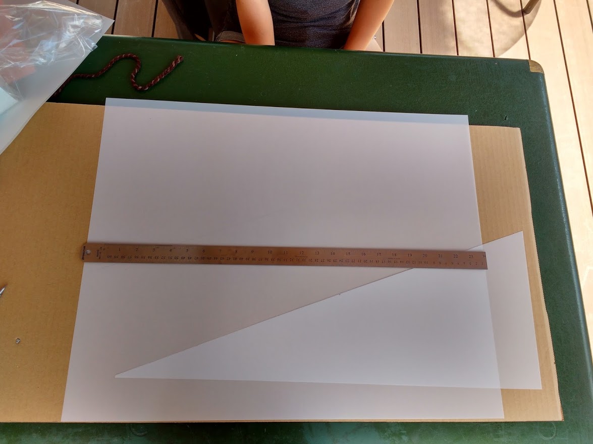
Each lamp shades was made from two right angle triangles cut from sheets of Dura-Lar polyester film. Unfortunately, I never wrote down dimensions for the lamp shade but the dimensions are not too critical. The ruler in the picture is 24” long.
Wooden Base
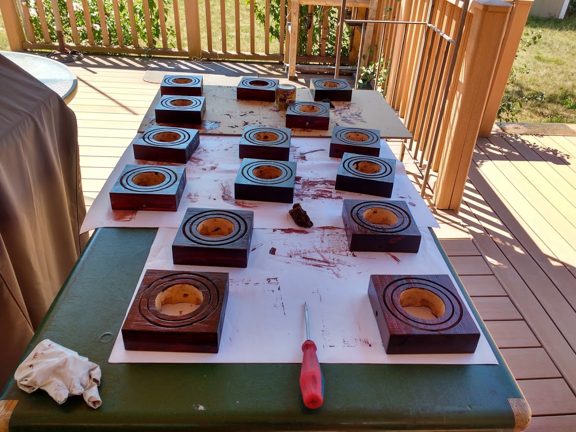
The wooden base is made from a 1-¾” x 5.5” x 5.5” block of wood. A 3” diameter hole was cut through the center of the wooden base to allow space for the battery pack and clearance for the bottom of the through hole solder joints. A 4” hole saw was used to create a slot for the inner lamp shade and a 5” hole saw was used to cut a slot for the outer lamp shade. The blocks were then stained with some random stuff we found in the garage.
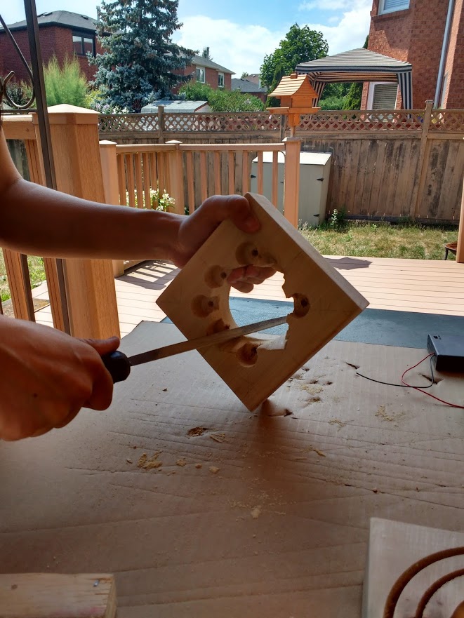
On the bottom, a 1” Forstner bit was used to cut out the corners of the circular through hole to allow the battery pack to fit snugly. A few extra holes were cut on the first base as we tried to figure out what would work best.
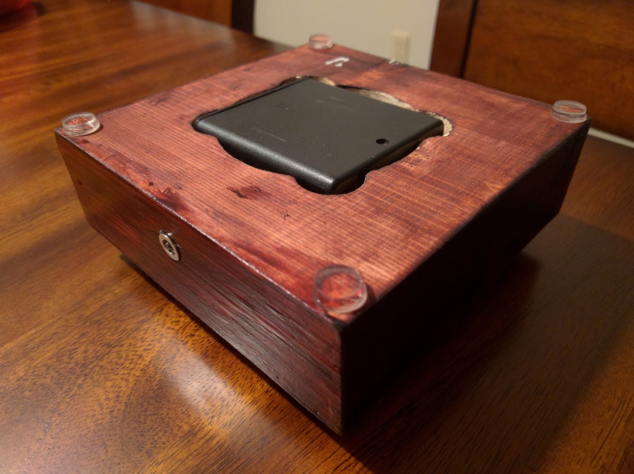
A hole was then drilled for the 2.1mm DC jack which was press fit into place.
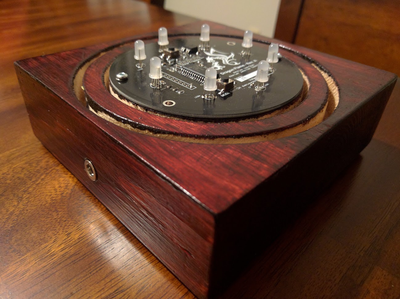
The boards were then fastened with 2 small wood screws.
Final Assembly
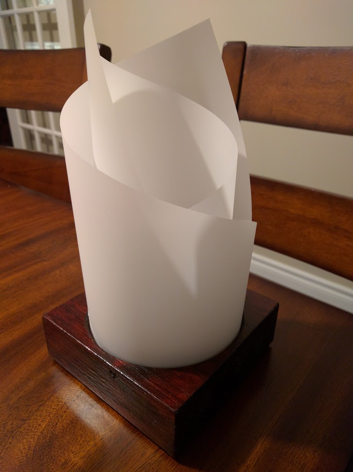
Two triangular pieces of Dura-Lar were then formed into cylinders with the long side of the triangle in the slot. The cylinders were then rotated so the sharp point was on the left and right sides with the DC jack facing the rear. Then a piece of cardboard was jammed into the slot to keep the Dura-Lar in place.

One thought on “PIC32 – Dragon Flame”